- This topic has 3 replies, 2 voices, and was last updated 4 months, 1 week ago by
 xeon.
xeon.
-
AuthorPosts
-
2026-03-19 at 6:31 pm #86693
Nathan Arditti
CustomerHello Verge3D Team and Community,
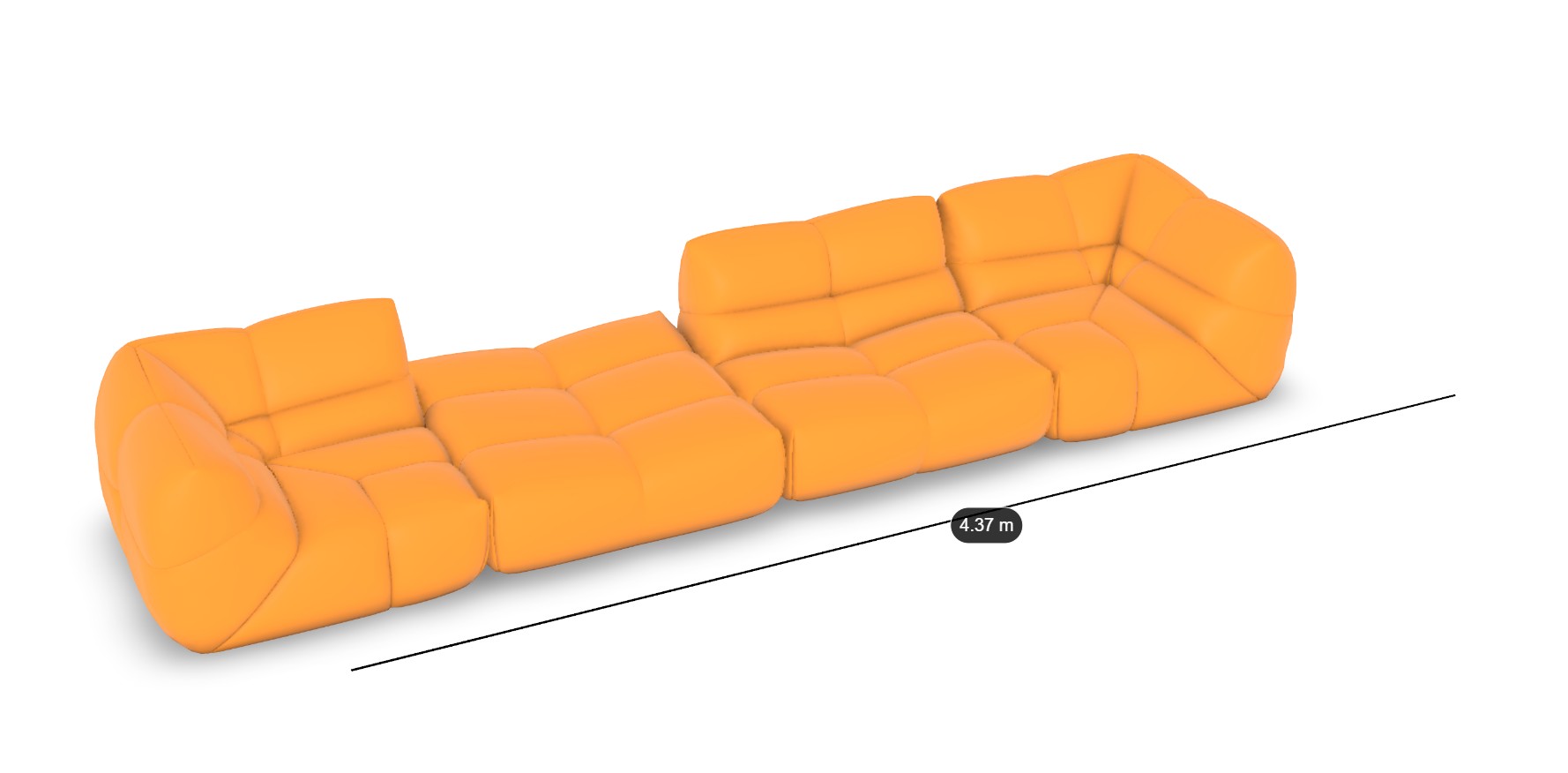
I am building a modular sofa configurator. Users can add and remove 5 different types of modules. I have encountered a major blocking issue regarding object naming and dimension tracking.
1. The Cloning Name Collision Issue
My current logic for naming clones is based on the count of active modules.The Problem: If I have modules named corner_1, corner_2, and corner_3, and I delete corner_2, my total count drops to 2. When I add a new module, the logic names it corner_3 again.
The Result: I end up with two objects named corner_3 in the scene.
Console log example: visible : corner_1, corner_3, corner_3
This naming collision prevents me from correctly identifying objects in my “visible modules” list and breaks my measurement calculations.2. Dynamic 3D Dimensions (L x W x H)
I need to display the overall dimensions of the sofa assembly in the 3D viewport.It must update in real-time whenever a module is added or removed.
I want to show a line for the total Length, Width, and Height.
I need floating annotations/labels at the center of these lines displaying the values.
My Questions:
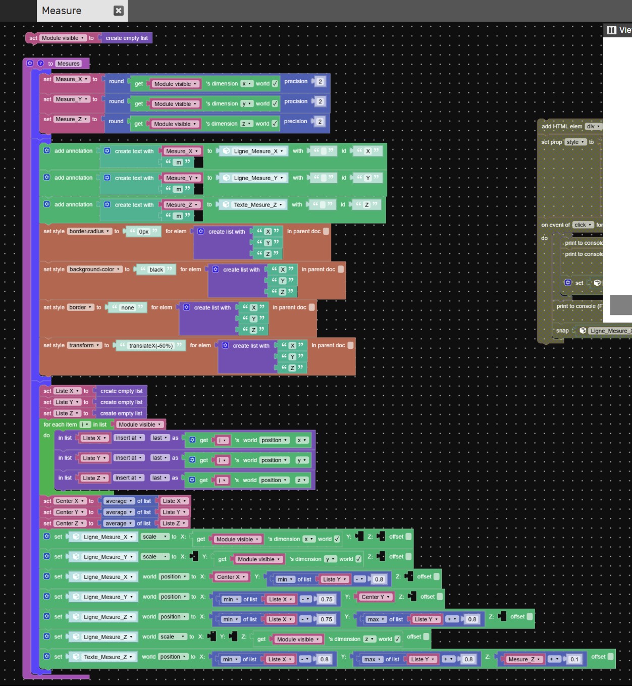
What is the best way to implement a persistent global counter for IDs that never resets or decreases, ensuring every clone has a strictly unique name regardless of deletions?
How can I calculate the “Global Bounding Box” of a list of specific objects (clones) to get the overall dimensions?
What is the most efficient way to render these dimension lines and labels so they follow the sofa’s bounds dynamically?
Any advice on the Puzzles logic or small JavaScript snippets to handle the bounding box would be extremely helpful !
You can try it here : https://v3d.net/1fk5
Attachments:
2026-03-19 at 7:44 pm #86695 xeonCustomer
For the naming part…you could simply clone your objects into a list.
set variable myclonelist > createlist with > cloneobject > my object
you can then add cloned and remove cloned objects from the list and the only thing you care about is the list length and the maging the list when you load in a new object or delete one… you don’t worry about the names…you worry about the list position only.with respect to box dimensions. If you take all your objects you want to measure and put them in a list you can use “get object dimensions” .
Since the clone naming is a list issue and the dimension are a list issue….simple fix.
-
This reply was modified 4 months, 1 week ago by xeon.
Xeon
Route 66 Digital
Interactive Solutions - https://www.r66d.com
Tutorials - https://www.xeons3dlab.com2026-03-20 at 11:55 am #86709CustomerIt worked and I don’t even know how !

Many thanks.
Have 2 more issues:
1) I don’t know why the black lines displaying the measurement values scale over the dimensions of my modules and don’t align correctly. (See attached video)
2) By default, when adding long text to a standard Verge3D annotation, the left side stays anchored to the 3D point and the dialog box stretches only to the right.
Goal: I need a workaround to make the annotation dialog expand symmetrically from the center (horizontally centered over the 3D anchor point) so the text box doesn’t just push to the right side.
I tried to use the puzzle “set style transform to “translateX(-50%)” for my annotation” and it didn’t work.
And I also tried to use this code in the CSS file which didn’t work :
.v3d-annotation-dialog {
transform: translateX(-50%) !important;
width: 250px !important;
white-space: normal !important;
text-align: center;
}Thanks in advance for your precious help

You can try it here : https://v3d.net/1fk5
2026-03-20 at 4:41 pm #86717xeonCustomer1) I don’t know why the black lines displaying the measurement values scale over the dimensions of my modules and don’t align correctly. (See attached video)
– I cant say with certainty but I would look into the following things: are your objects scale “applied”, meaning is scale set to 1; is your object transform within the 3d volume; do you have vertices or edges that are a part of the object mesh outside the 3d volume. If the answer is no to all of these… then I would retest how your scene using basic cubes to ensure the measuring lines are working properly. If you get to this point and its still not working….package up the file and send over and I will take a look.2) By default, when adding long text to a standard Verge3D annotation, the left side stays anchored to the 3D point and the dialog box stretches only to the right.
The default V3D annotations are really meant for short strings. However you can use the CSS to control how you want to display them if you need additional room, formatting, etc….see this link: https://www.soft8soft.com/docs/manual/en/introduction/Personalizing-Verge3D-Apps.html#annotationsThere is a thread on the forum that goes through how to create a more custom annotation that might be what you need:
Xeon
Route 66 Digital
Interactive Solutions - https://www.r66d.com
Tutorials - https://www.xeons3dlab.com -
AuthorPosts
- You must be logged in to reply to this topic.